Infrastructure Architecture
Infrastructure Architecture represents the solution level. It is the representation of the components to be deployed - their specifications, configurations, features and functionalities and nominated Original Equipment Manufacturers (OEMs) or vendors that meet these requirements. These Infrastructure systems (and / or their components) comprise the hardware and software elements of a Services Catalogue.
Vendors and service providers sell their systems by looking for opportunities that match their own service catalogue - that is, they inherently start from a bottom-up approach. The better ones understand their customers' businesses and the potential benefits their capabilities have for a client organisation's functions and processes. Optimally, they also understand, or will seek to understand, the implications for intergating their capabilities with other components of an ICT environment. In other words they qualify an opportunity via a top-down validation that their offering matches a client organisation's business objectives and strategy. An outsource provider, one who is undertaking ICT design and management on their client's behalf, should be applying a top-down approach and starting at the Business level architecture.
Bottom-up design can have merit where ICT innovations and initiatives can contribute new value to an organisation. However, such innovations and initiatives need to be qualified against business objectives through the application of a top-down assessment of the merits and justification of any such change in context of an organisation's business goals and strategies. An Architecture Development Method (such as TOGAF) which forms a key element of an Architecture Metamodel, provides a cyclical approach and largely reconciles the top-down vs. bottom-up design approaches.
The Infrastructure Architecture is the final level of network design. It captures the physical and logical infrastructure of the enterprise. This infrastructure includes all of the physical communications and it assets, the buildings, environments and other material assets.
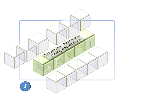
The primary classifications applied to network Infrastructure can be:
- Interconnectivity
- User Interfaces. A user may be a machine (e.g. for M2M).
Infrastructure primary classifications - Interconnectivity
Key Characteristics: Shared components of a network that allow for the interaction of users over a network.
Network connectivity is determined by the Systems Architecture, which in turn is influenced by Information Architecture defined from the Business Architecture. Interconnectivity forms the basis for the consideration of User Interface options. User Interfaces should not be the primary determinant of Interconnectivity.
Legacy infrastructures, including User Interfaces, need to be considered where they form a component of an overall Architecture. They typically provide design inputs to a new or changed architecture, to consider and accommodate interdependencies.
Legacy elements should not be retro-fitted to a newly described Business or Information Architecture:
- they are external inputs,
- their retention can be considered in terms of qualified value to a Business Architecture,
- any alternatives for a Target or Future State architecture can be identified and qualified, and
- A proposed architecture can be fully validated and justified inclusive of new and retained elements within a holistic architecture.
Interconnectivity can be classified as:
- Fixed,
- Wireless,
- Mobile.
Wireless is defined separately to Mobile, as it is private infrastructure vs. the public infrastructure of carrier mobile networks which are less able to be customised for individual contexts.
Infrastructure primary classifications - Interfaces
Key Characteristics: Customer-specific point of interaction between users via a network. They are may be further classified as:
- Dedicated for specific users (e.g. handset, tablet, laptop etc),
- Shared between groups of users (e.g. videoconferencing, audio-visual), and
- Used by multiple entities (e.g. kiosks, ATMs, EFTPOS terminals ).
User Interfaces are include both Mission Systems and Support Systems classifications within the Systems Architecture definitions.
Management tools have a specific User Interface (and likely interconnectivity) . These are defined by these sub-categories within the Support System classification of a Systems Architecture.
Service and network management and monitoring personnel, however provided, form specific user grouping(s) . They are a part of an Architecture.
Interfaces also form a component at the Information Architecture level. At the Information Architecture level, the interfaces are
described in terms of the information format at the source, and the format required at its destination - such as human-readable vs machine readable,
text vs speech etc.
The information interface descriptions consider the users' requirements, whether they are human or machine, fixed, location independent or mobile. At the Infrastructure Architecture level, interfaces are described in terms of the actual device requirements.
Systems mapped to Infrastructure Architecture
It may be tempting to argue that user requirements will determine the Infrastructure and Systems architectures - for example, a customer's users requirements include a requirement for remote intranet access to business apps.
This is reverse engineering. User requirements should be based on Business requirements as described in the top level Business Architecture.
User requirements can, and will, influence architectures - specifically for retained legacy components, however these should be tested against a Business Architecture to validate their retention, even if it is a purely cost issue. That provides substantiation of architecture decisions and validation at multiple levels.
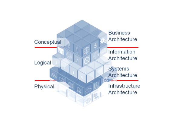
Infrastructure Architecture is the physical definition of the logical Systems Architecture classifications which itself is an extension of the conceptual Business Architecture. The Information Architecture applies at a logical level also:
Infrastructure secondary classifications
As the level of detailed architecture, Infrastructure will typically be categorised at multiple levels of increasing detail, as will be determined by the scope of the architecture effort. This Taxonomy goes to a secondary level only, as the diversity increases the wider the scope being described.
While purists will argue the defintions of, and delineations between the categories within this classification, the technicalities of the differentiation (such as a LAN being Ethernet at Layers 1 and 2 in the OSI model) are changing.They are generally understood and accepted as descriptors, and describing architectures is a key purpose of the EA discipline.
For taxonomical purposes, the following defintions apply. The more oblique terms such as BAN, DAN etc. are hereby ignored. A future whereby any-to-any connection of smart, media-rich and wireless devices across generic networks are the norm may see the demise of these naming conventions:
- LAN. Networks connecting end devices to provide shared access to printers, file servers and other services. LANs may be a component of larger networks such as larger LANs or WANs connecting many devices within an organisation to each other and/or to the Internet.
- WAN. Multiple, widely dispersed and interconnected LANs that form a definable entity through common aspects - ownership, IP schema, management etc. This definition doesn't work with the Internet as the world's biggest WAN, but these pages are not about architecting the Internet.
- MAN. A WAN limited in its distribution to a common metroploitan geography. Why the distinction between a WAN and a MAN? As a description it provides a valuable mental picture and means for interpreting an architecture.
- SAN.An Area Network with dedicated storage and archiving capability.
- CAN. A LAN or WAN distributed over a campus-like facility such as a military base, an airport or (surprise) a university campus(!).
- Desktop. In its broadest sense, Desktop can be used for, or substituted with another naming convetion, to incoprorate end points where transactions are conducted, for example kiosks, ATMs, RFID etc.
- Remote Access, being access to enterprise information assets from a point that is external to an organisation's own infrastructure.
- Off Net. The interconnection to public domains across public infrastructure, or between two or more separate enterprise networks.
Design Parameters
- Statement of Work. The purpose of an SOW is to communicate the requirements and standards for work to be carried out under a Contract and to allocate work responsibilities between the Customer and a contractor.
- Functional Performance Specification. An FPS provides the detailed requirements that a customer wishes to be met in
accordance with priorities - being the relative importance of each requirement.
A Baseline architecture should address essential requirements for a least-cost proposition. Important, and possibly desirable criteria should be considered where they do not impose additional cost or where it is considered to offer a qualified competitive advantage.
An FPS sets out the specific functions required for a transformed system (what and how well).
An SoW sets out everything needed to do as a part of a contract (when, how). - Performance Framework. Sets out the Service Levels, their application and the governance supporting the management of the Performance Framework.
A Systems Breakdown Structure provides an exhaustive, hierarchical structure of deliverables (physical, functional or conceptual)
that make up a project, arranged in whole-part relationships.
The SBS is intended to capture each of the component products and services deliverables and their inter-relationships.
The SBS also informs the Work Breakdown Structure - ensuring that each element has an assigned owner.
The SBS will provide a schematic representation of the entire environment.
A Work Breakdown Structure provides a common framework for the natural development of overall planning and control and is the basis for dividing the design effort into definable increments from which Statements of Work can be developed and technical, schedule and cost reporting, via the Cost Breakdown Structure, can be established.